


Introduction
One of my favorite subjects back when studying CCNA Security was VPNs, especially Site-to-Site VPNs. At first glance this can seem daunting but with some practice and repetition you will overcome the vast amount of information.
This blog post, we are going to configure a Site-to-Site VPN between two Cisco Enterprise Routers. For this I will be using Packet Tracer network simulator with 2811 Routers
you can sign up for a Cisco Netacad account at the link below to download packet Tracer.
skillsforall.com/course/getting-started-cis..
another option is GNS3 network Simulator but you will need your own Cisco IOS image.
Setup/Planning
The following screenshot shows our topology, we want to create a site-to-site VPN between R1 and R2 to encrypt our LAN traffic across the internet (ISP Router)
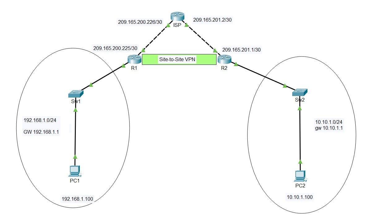
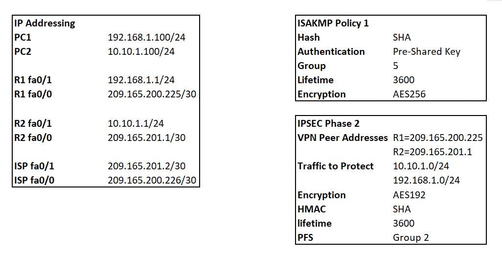
The following shows the IP addressing for all interfaces and the plan for our Site-to-Site VPN
R1 Base config
R1(Config)#hostname R1
R1(Config)#int fa0/1
R1(Config-if)#ip address 192.168.1.1 255.255.255.0
R1(Config-if)#exit
R1(Config-if)#int fa0/0
R1(Config-if)#ip address 209.165.200.225 255.255.255.252
R1(Config-if)#exit
R1(Config)#ip route 0.0.0.0 0.0.0.0 209.165.200.226
R1(Config)#wr
R2 Base Config
R2(Config)#hostname R2
R2(Config)#int fa0/1
R2(Config-if)#ip address 10.10.1.1 255.255.255.0
R2(Config-if)#exit
R2(Config-if)#int fa0/0
R2(Config-if)#ip address 209.165.201.1 255.255.255.252
R2(Config-if)#exit
R2(Config)#ip route 0.0.0.0 0.0.0.0 209.165.201.2
R2(Config)#wr
ISP Base Config
ISP(Config)#hostname ISP
ISP(Config)#int fa0/1
ISP(Config-if)#ip address 209.165.201.2 255.255.255.252
ISP(Config-if)#exit
ISP(Config-if)#int fa0/0
ISP(Config-if)#ip address 209.165.200.226 255.255.255.252
ISP(Config-if)#exit
ISP(Config)#wr
Build Process
The Site-to-Site IPSEC VPN process creates two tunnels:
IKE Phase 1 - Management Tunnel
IKE Phase 2 - Data Tunnel
we will need to define:
isakmp policy for phase 1 negotiation
transform-set for phase 2 negotiation
define our interesting traffic with a crypto map ACL (traffic to be encrypted)
create a crypto map to bind everything together and apply to outgoing interfaces of R1/R2
Test and verify
IKE Phase 1 (ISAKMP Policy)
This tunnel is purely used for the Routers to talk directly to each other to form the Phase 1 tunnel, this is then used to share management traffic related to creation and running of the VPN. NO transfer of data packets takes place on this tunnel that we want to encrypt between our networks.
HAGLE
To form a phase 1 tunnel both routers must agree on the following (I use HAGLE to remember the variables):
Hash (MD5/SHA)
Authentication (Pre-shared key/Digital Certificates)
Group (DH)
Lifetime of tunnel (seconds)
Encryption (DES/3DES/AES)
The above is used to create a Crypto ISAKMP Policy. You can have more then one policy with varying attributes. As long as routers at each end of the VPN have a matching policy set they can form a Phase1 tunnel.
R1(config)#crypto isakmp policy 1
R1(config)#Encryption AES 256
R1(config)#group 5
R1(config)#lifetime 3600
R1(config)#authentication pre-shared key
R1(config)#hash sha
R2(config)#crypto isakmp policy 1
R2(config)#Encryption AES 256
R2(config)#group 5
R2(config)#lifetime 3600
R2(config)#authentication pre-shared key
R2(config)#hash sha
We will set the Pre Shared Key for both R1 and R2, remember this must match or you will never form a Phase 1 Tunnel:
R1(config)#crypto isakmp key SuperSecret! address 209.165.201.1
R2(config)#crypto isakmp key SuperSecret! address 209.165.200.225
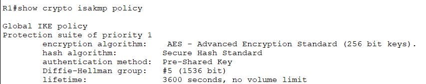
Verify your phase 1 policy with the following command:
IPSEC Phase 2 (Transform-Set)
We now need to create our "transform-set" for the phase 2 tunnel again both routers must agree on matching policy for a tunnel to form.
- Encryption - AES 192
- HMAC - SHA
- lifetime - 3600 (Set in Crypto Map)
- PFS - Group 2 (Set in Crypto Map)
R1(config)#crypto ipsec transform-set MYTSET esp-aes 192 esp-sha-hmac
R2(config)#crypto ipsec transform-set MYTSET esp-aes 192 esp-sha-hmac
Verify your Transform-set with the following:
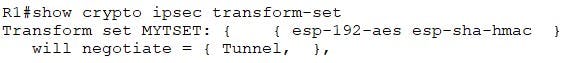
Crypto ACL
The crypto ACL is used to define the "interesting" traffic we want to traverse the VPN. This is written as an ACL. Below is a reminder of the traffic source and destinations we want to encrypt with our VPN:
- 192.168.1.0/24 going to 10.10.1.0/24 (R1 -> R2)
- 10.10.1.0/24 going to 192.168.1.0/24 (R2 -> R1)
R1(config)#access-list 100 permit ip 192.168.1.0 0.0.0.255 10.10.1.0 0.0.0.255
R1(config)#access-list 100 permit ip 10.10.1.0 0.0.0.255 192.168.1.0 0.0.0.255
Crypto Map
The crypto map binds everything we have created above together with a few additions:
Transform Set (MTSET)
match ACL (100)
Lifetime (3600)
PFS Group (2)
R1(config)#crypto map MYMAP 1 ipsec-isakmp
R1(config-crypto-map)#match address 100
R1(config-crypto-map)#set pfs group2
R1(config-crypto-map)#set peer 209.165.201.1
R1(config-crypto-map)#set transform-set MYTSET
R1(config-crypto-map)#set security-association lifetime seconds 3600
R2(config)#crypto map MYMAP 1 ipsec-isakmp
R2(config-crypto-map)#match address 100
R2(config-crypto-map)#set pfs group2
R2(config-crypto-map)#set peer 209.165.200.225
R2(config-crypto-map)#set transform-set MYTSET
R2(config-crypto-map)#set security-association lifetime seconds 3600
Apply Crypto Map
Finally we need to now apply our crypto map to our outgoing interface the VPN will be established on. In this case our outgoing on both R1/R2 is FA0/0
R1(config)#interface fa0/0
R1(config-if)#crypto map MYMAP
R2(config)#interface fa0/0
R2(config-if)#crypto map MYMAP
Verify your crypto map and ACL with the following:
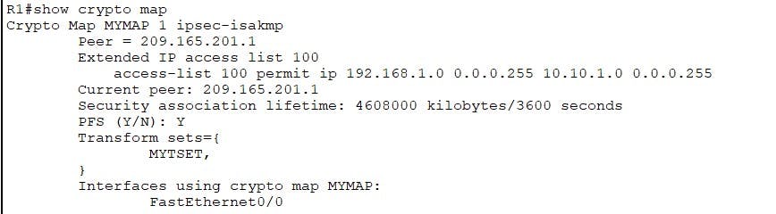
Test and Verify
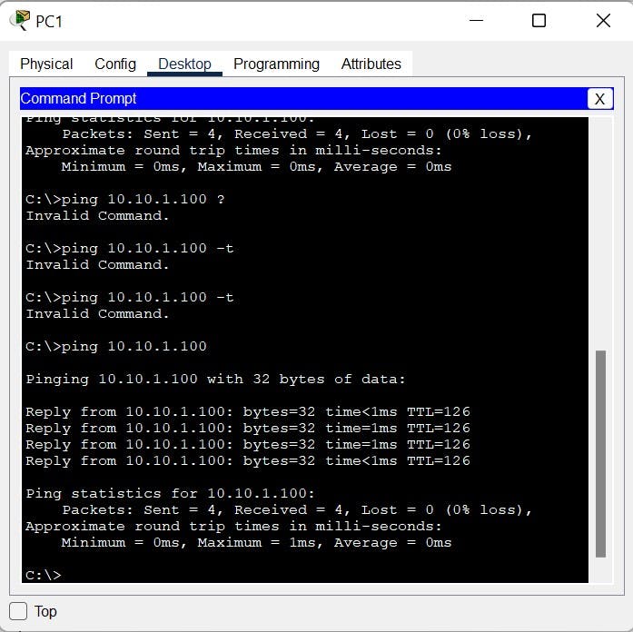
Now our VPN configuration is complete. We will test connectivity by sending Pings from PC1 to PC2 to generate some traffic that will trigger the VPN.
PC1 to PC2
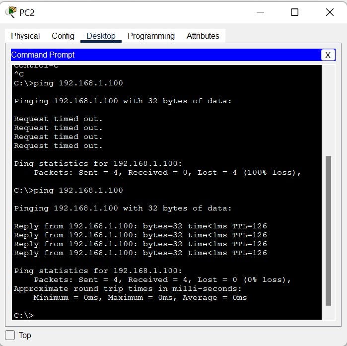
PC2 to PC1
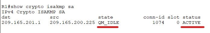
We can run the following commands to verify the phase 1 tunnel, We are looking for:
- state= QM_IDLE (tunnel is built)
- status Active (Tunnel is active within lifetime)
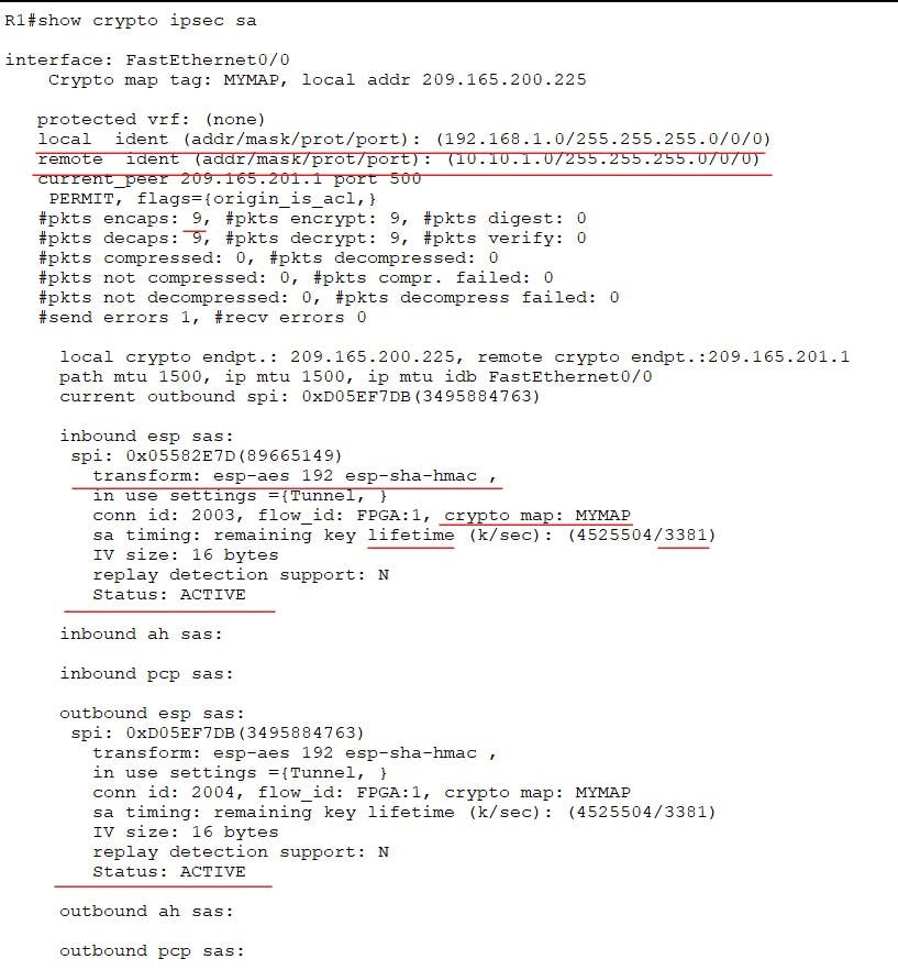
We can use the following to verify phase 2 and actually see traffic is being encrypted. Take note of the source address and destination, they match the traffic we wanted to encrypt via the crypto map ACL. We can also verify the transform-set and crypto maps we created are being used. At the bottom we also have Status ACTIVE. The more pings we send you will notice the encrypted packets count will increase.
and there we go a site-to-site IPSEC VPN between two Cisco routers. I hope you enjoyed this post, please leave a like if it has helped you or reach out in the comments section!
For cryptography basics please see my previous blog post here: switchitup.tech/cryptography-basics-securin..
In a future blog post I will cover site-to-site between ASA firewalls so watch-this-space!